Three Phase Transformer
Three phase transformers are used throughout industry to change values of three-phase voltage and current. Since three-phase power is the most common way in which power is produced, transmitted, and used, an understanding of how three phase transformer connections are made is essential.
- A three phase transformer is constructed by winding three single phase transformers on a single core.
- These transformers are put into an enclosure which is then filled with dielectric materials such as air, plastic or oil.
- The dielectric material performs several functions.
- Since it is a dielectric, a non-conductor of electricity, it provides electrical insulation between the windings and the case.
- It is also used to help provide cooling and to prevent the formation of moisture, which can deteriorate the winding insulation.
Three-Phase Transformer Connections
- Three-phase transformers can consist of either three separate single-phase transformers, or three windings on a three-legged, four-legged, or five-legged core.
- The high-voltage and low-voltage sides can be connected independently in either wye or delta.
- As a result, the ratio of the 3‑phase input voltage to the 3‑phase output voltage depends not only upon the turns ratio of the transformers, but also upon how they are connected.
There are only 4 possible transformer combinations:
- Delta-to-Delta Connection: It is used for industrial applications.
- Delta to Wye Connection: It is popular for stepping down transmission lines to four-wire services when neutrals are needed.
- Wye to Delta Connection: It is used to step-down utilities high line voltages.
- Wye-to-Wye Connection: It is commonly used for interior wiring systems
Y/Y Connection: A Y/Y connection for the primary and secondary windings of a three-phase transformer is shown in the figure below.

Y/Y connected three-phase transformer
- The line-to-line voltage on each side of the three-phase transformer is √3 times the nominal voltage of the single-phase transformer.
- The main advantage of Y/Y connection is that we have access to the neutral terminal on each side and it can be grounded if desired.
- Without grounding the neutral terminals, the Y/Y operation satisfactory only when the three-phase load is balanced.
- The electrical insulation is stressed only to about 58% of the line voltage in a Y-connected transformer.
Y/Δ Connection: This connection as shown in figure below is very suitable for step-down applications.

Y/Δ connected three-phase transformerThe secondary winding current is about 58% of the load current.
- On the primary side the voltages are from line to neutral, whereas the voltages are from line to line on the secondary side.
- Therefore, the voltage and the current in the primary are out of phase with the voltage and the current in the secondary.
- In a Y/Δ connection the distortion in the waveform of the induced voltages is not as drastic as it is in a Y/Y-connected transformer when the neutral is not connected to the ground the reason is that the distorted currents in the primary give rise to a circulating current in the Δ-connected secondary.
Δ/Y Connection: This connection as shown in figure below is proper for a step-up application.
Δ/Y connected three-phase transformer

- However, this connection is now being exploited to satisfy the requirements of both three-phase and the single-phase loads.
- In this case, we use a four-wire secondary.
- The single-phase loads are taken care of by the three line-to-neutral circuits.
- An attempt is invariably made to distribute the single-phase loads almost equally among three-phases.
Δ/Δ Connection: as shown below the three transformers with the primary and secondary windings connected as Δ/Δ.
Δ/Δ connected three-phase transformer

- The line-to-line voltage on either side is equal to the corresponding phase voltage. Therefore, this arrangement is useful when the voltages are not very high.
- The advantage of this connection is that even under unbalanced loads the three-phase load voltages remain substantially equal.
- This disadvantage of Δ/Δ connection is the absence of a neutral terminal on either side.
- Another drawback is that the electrical insulation is stressed to the line voltage.
- Therefore, a Δ-connection winding requires more expensive insulation than a Y-connected winding for the same power rating.
Example-1: Three single‑phase transformers are connected in delta‑delta to step down a line voltage of 138 kV to 4160 V to su-pply power to a manufacturing plant. The plant draws 21 MW at a lagging power factor of 86 percent. Calculate the following.
- (i) Apparent power drawn by the plant,
- (ii) Apparent power furnished by the HV line,
- (iii) The current in the HV lines,
- (iv) The current in the LV lines
- (v) The currents in the primary windings of each transformer
- (vi) The currents in the secondary windings of each transformer
- (vii) The load carried by each transformer
Solution: (i) The appearent power drawn by the plant is:
S= P Cos φ = 21/0.86 = 24.4 MVA
(ii) The transformer bank itself absorbs a negligible amount of active and reactive power because the losses and the reactive power associated with the mutual flux and the leakage fluxes are small. So, the apparent power furnished by the HV line is also 24.4 MVA.
(iii) The current in each HV line is :
(iv) The current in LV lines is :
(v) The current in each primary winding is:
(vi) The current in each secondary winding is:
(vii) The load carried by each transformer
- Plant load is balanced, hence each transformer carries one‑third of the total load: 24.4/3 = 8.13 MVA
OR
- The individual transformer load can also be obtained by multiplying the primary voltage times the primary current:
Example-2: : Determine the interrupting capacity, in amperes, of a circuit breaker or fuse required for a 75 kVA, three phase transformer, with a primary of 480 volts delta and secondary of 208Y/120 volts. The transformer impedance (Z) = 5%.
Solution:
Primary circuit of the transformer is the only winding being interrupted. Hence the secondary voltage is not used in the calculation.
If the secondary is short circuited (faulted),
- Normal Full Load Current = Volts Amps / (Square root (3) * Line volts) = 75,000 VA / (Square root (3) * 480 V) = 90 Amps
- Maximum Short Circuit Line Current = (Full load amps / 5%) = (90 Amps / 5%) = 1800 Amps
Therefore, the breaker or fuse would have a minimum interrupting rating of 1,800 amps at 480 volts.
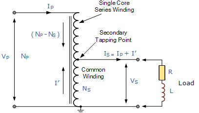
Autotransformer
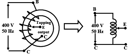
This single winding is “tapped” at various points along its length to provide a percentage of the primary voltage supply across its secondary load. Then the autotransformer has the usual magnetic core but only has one winding, which is common to both the primary and secondary circuits.
Therefore in an autotransformer, the primary and secondary windings are linked together both electrically and magnetically. The main advantage of this type of transformer design is that it can be made a lot cheaper for the same VA rating, but the biggest disadvantage of an autotransformer is that it does not have the primary/secondary winding isolation of a conventional double wound transformer.
The section of winding designated as the primary part of the winding is connected to the AC power source with the secondary being part of this primary winding. An autotransformer can also be used to step the supply voltage up or down by reversing the connections. If the primary is the total winding and is connected to a supply, and the secondary circuit is connected across only a portion of the winding, then the secondary voltage is “stepped-down” as shown
This single winding is “tapped” at various points along its length to provide a percentage of the primary voltage supply across its secondary load. Then the autotransformer has the usual magnetic core but only has one winding, which is common to both the primary and secondary circuits.
Therefore in an autotransformer the primary and secondary windings are linked together both electrically and magnetically. The main advantage of this type of transformer design is that it can be made a lot cheaper for the same VA rating, but the biggest disadvantage of an autotransformer is that it does not have the primary/secondary winding isolation of a conventional double wound transformer.
The section of winding designated as the primary part of the winding is connected to the AC power source with the secondary being part of this primary winding. An autotransformer can also be used to step the supply voltage up or down by reversing the connections. If the primary is the total winding and is connected to a supply, and the secondary circuit is connected across only a portion of the winding, then the secondary voltage is “stepped-down” as shown.
The voltages developed in the windings are dependent on the flux linkages. The windings are wound on the same magnetic core so they link the same flux.
- V1 / N1= V2 / N2.
So whenever voltage V1 exist across primary winding, then voltage V2 will be induced across the secondary winding irrespective of changes in connections.
Similarly the magnetic circuit demands that mmf should be balanced. It implies the primary side ampere turn should equal the secondary side ampere turn.
- I1 . N1= I2 . N2
Here,
- Autotransformers are also used for voltage regulation in distribution networks, for starting of induction motors and as lighting dimmers. Autotransformers are also used in electric traction.
- One main disadvantage about autotransformer is that the primary and secondary are electrically connected. So the electrical disturbance i.e. high voltage transients from one side can be easily transmitted to the other side.
- The other disadvantage is that the impedance of the autotransformer is considerably low, so the short circuit current will be more.
- More over an open circuit in common winding results in full primary side voltage across the load which is harmful.
Disadvantages of an Autotransformer
- The main disadvantage of an autotransformer is that it does not have the primary to secondary winding isolation of a conventional double wound transformer. Then an autotransformer can not safely be used for stepping down higher voltages to much lower voltages suitable for smaller loads.
- If the secondary side winding becomes open-circuited, current stops flowing through the primary winding stopping the transformer action resulting in the full primary voltage being applied to the secondary terminals.
- If the secondary circuit suffers a short-circuit condition, the resulting primary current would be much larger than an equivalent double wound transformer due to the increased flux linkage damaging the autotransformer.
- Since the neutral connection is common to both the primary and secondary windings, earthing of the secondary winding automatically Earth’s the primary as there is no isolation between the two windings. Double wound transformers are sometimes used to isolate equipment from earth.
The autotransformer has many uses and applications including the starting of induction motors, used to regulate the voltage of transmission lines, and can be used to transform voltages when the primary to secondary ratio is close to unity.
An autotransformer can also be made from conventional two-winding transformers by connecting the primary and secondary windings together in series and depending upon how the connection is made, the secondary voltage may add to, or subtract from, the primary voltage.
Comments
Post a Comment